Installation Instructions for
EIS-1X, EIS-3X, EIS-5X and
EIS-8X Series Sealing Plugs
Hole Preparation
- Use the catalogue sheet for the product you are installing to determine the correct counterbored hole (D2) and drilled hole (D3) size and tolerance.
- Hole roundness must be held to within 0.05mm.
- Bore roughness must be between Rz (RMS) 10 – 30 µm especially for hard materials.
- Avoid spiral or longitudinal grooves as these may affect plug performance.
- Be sure each bore is clean and free from any and all cutting oils, chips, etc.
Installation Procedure
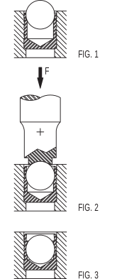
- Insert the EIS plug into the counterbored hole with the ball facing out,
seated against the counterbore shoulder. - It is important that the correct drill and counterbore size are selected so
that the plug is properly supported during installation and a good seal is
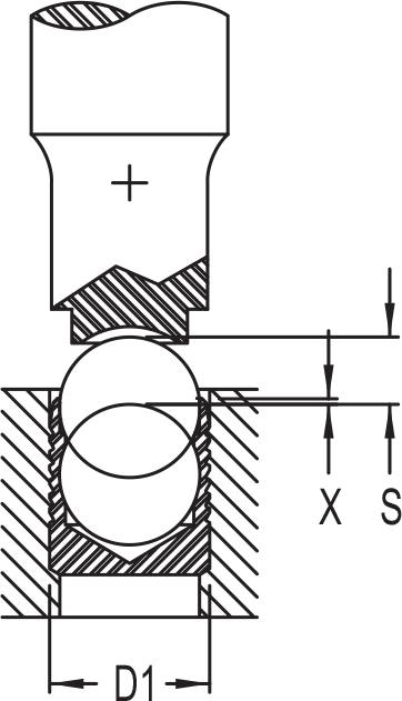
obtained. - Press the ball into the sleeve so that the top of the ball is slightly below the
top of the sleeve (see FIG. 2 and 3). Approximate values for S (stroke) and X
are listed in the table below. - Be sure to purchase the correct installation tool for each plug size selected.
- EIS-1X, 3X, 5X, 8X Series plugs can be installed using a hammer and the
correct hand installation tool. An arbor or an air hammer with the correct air
hammer installation tool can also be used. - The installation of the EIS-1X, 3X, 5X, 8X Series plugs can also be automated.
Installation Instructions for
EIS-RST, RSO & LRST Sealing
and Orifice Plugs
Hole Preparation
- Use the catalogue sheet for the product you are installing to determine the correct drilled hole (D3) size and tolerance.
- Hole roundness must be held to within 0.05mm.
- Bore roughness must be between Rz (RMS) 10 – 30 µm especially for hard materials.
- Avoid spiral or longitudinal grooves as these may affect plug performance.
- Be sure each bore is clean and free from any and all cutting oils, chips, etc.
Installation Procedure
- Always work in a clean work area.
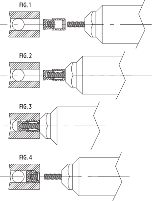
- EIS RST or RSO Series Sealing Plugs are designed to be used as received. Do not clean or lubricate the plug or the pin. (Fig. 1)
- Push the threaded arbor against the EIS Pullplug “patent pending”. The arbor will automatically thread into the sealing plug. (Fig. 2)
- Insert the plug into the hole. Be sure the nose piece is pushed against the workpiece and is perpendicular.
(Fig. 3) - Activate the tool to expand the plug. The threaded arbor will pull the pin to a preset depth and then automatically and unscrew itself from the pin (Fig. 4)
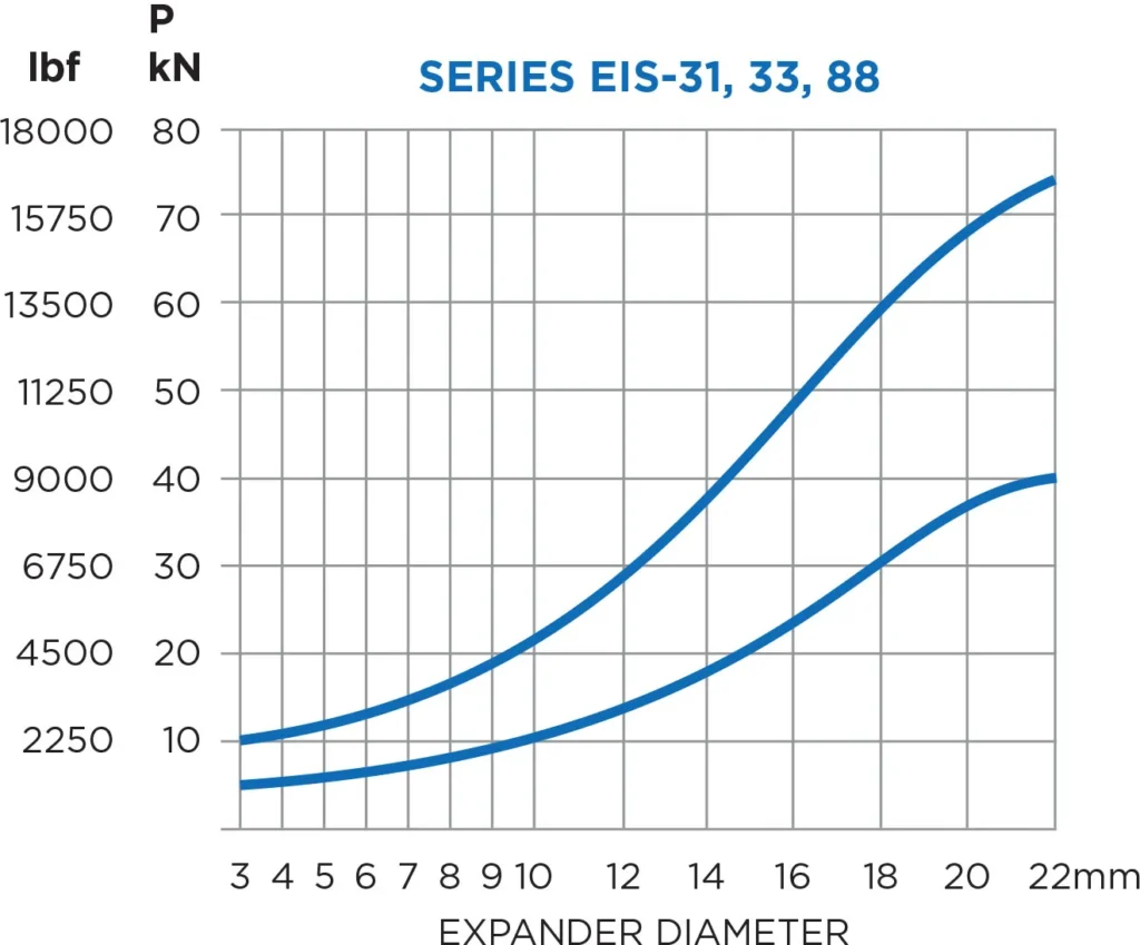
- Be sure to purchase the correct installation tool for each plug size selected.
Removal
- Using a punch, drive the expansion pin out of the plug.
- Drill out the plug and remove the expansion pin.
- Drill the hole for the next larger size EIS RST or RSO Series Pullplug.
- Be sure to remove all chips, plug remnants and any grease or oil from the hole.
- Install a new EIS RST or RSO Series Pullplug.